LED driver focus
Materials chosen for compact housings, dielectric safety, and repeatable heat dissipation.
LED driver thermal pads, conductive sheets, and electrical insulation materials for reliable heat dissipation in compact lighting electronics. We support 1–6 W/mK conductivity, adhesive options, and custom die-cut shapes for OEM assemblies.
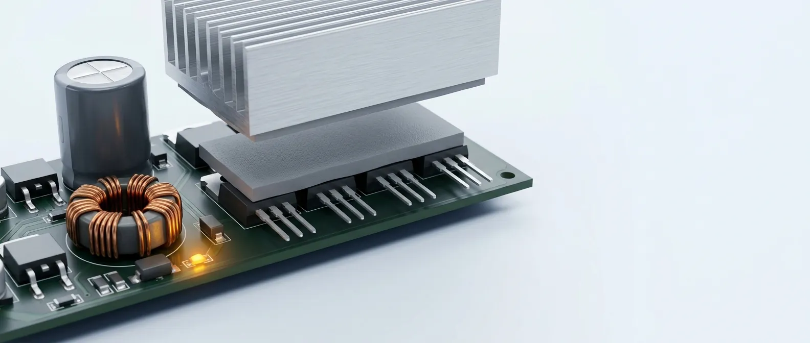
An LED driver is a small switch-mode power supply sealed inside the luminaire. The switching MOSFET, the rectifier stage and the control IC all dump heat into an enclosed housing that has no airflow of its own, and the only way that heat can leave is by conduction: through the component case, into the metal enclosure, and out to ambient air. LED driver boards create localized heat around semiconductors, magnetic parts, and enclosed housings. Poor thermal paths can shorten driver life and create performance drift in lighting systems.
That path fails at its weakest layer. A bare PCB or component tab never sits perfectly flat against the housing, and the air gap that remains — even a fraction of a millimetre — conducts almost nothing. The thermal interface becomes the bottleneck of the entire cooling path, which is why the thermal pad matters more than any other single material choice in the stack-up.
The cost of getting it wrong shows up slowly. Sustained over-temperature shortens the life of the driver's electrolytic capacitors, and capacitor wear-out is what usually ends a driver's service life — long after the luminaire has left the factory. A correctly specified LED driver thermal pad keeps interface resistance low, holds off the voltage between a live tab and a grounded housing, and keeps the driver inside its rated temperature for years.
We supply LED driver thermal pads and electrical insulation materials to your specification — cut, die-cut, and converted for OEM production.
Every watt the switching stage loses has to travel the same road. The junction temperature is whatever the ambient air is, plus the sum of every thermal resistance along that road.
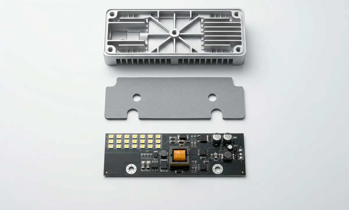
Heat leaves the silicon junction through the package case, crosses the interface into the heatsink or metal housing, and only then reaches ambient air. Most of those layers are fixed before the pad is ever chosen — the die, the package, the enclosure geometry are set by the board and the luminaire design.
The interface is the one layer left open, and it is also the one most often left to an air gap. A silicone thermal pad or LED driver insulation sheet in that gap cuts interface resistance sharply compared with still air, at a material cost of a few cents per driver.
Thermal pad conductivity selection starts from the measured case temperature, not from the catalogue. A driver running 15 °C over target in a sealed indoor housing usually needs its air gap closed properly more than it needs a higher-conductivity compound. The table below maps common LED driver types to the grades we supply for them.
| Driver type | Grade | Conductivity | Common thickness |
|---|---|---|---|
| Indoor / general-purpose driver | CP100 | 1.0 W/m·K | 0.5–1 mm |
| LED driver housings, compact cooling stacks | LED-DRV | 2.0 W/m·K | 0.5–2 mm |
| General LED driver heat dissipation | CP200 | 2.0 W/m·K | 0.5–3 mm |
| Driver transformer / SMPS-side | CP150 | 1.5 W/m·K | 0.5–2 mm |
| Potted, outdoor, or high-wattage driver | CP300 | 3.0 W/m·K | 0.5–3 mm |
| High-bay / industrial driver, MOSFET & IGBT stage | CP600 | 6.0 W/m·K | 0.5–3 mm |
Higher conductivity costs more and buys less than closing the air gap properly. Match the grade to the measured case temperature, not to the largest number on the datasheet.
All six grades are supplied as sheet with or without adhesive backing, and every grade can be die-cut to your drawing. Technical datasheets are linked per grade.
| Grade | Conductivity | Dielectric strength | Thickness options | Adhesive | Datasheet |
|---|---|---|---|---|---|
| CP100 | 1.0 W/m·K | 4.0 kV/mm | 0.5 / 1 / 2 / 3 mm | Adhesive or plain | TDS |
| CP150 | 1.5 W/m·K | 4.5 kV/mm | 0.5 / 1 / 2 mm | Adhesive or plain | TDS |
| CP200 | 2.0 W/m·K | 5.0 kV/mm | 0.5 / 1 / 2 / 3 mm | Adhesive or plain | TDS |
| CP300 | 3.0 W/m·K | 6.0 kV/mm | 0.5 / 1 / 2 / 3 mm | Adhesive or plain | TDS |
| CP600 | 6.0 W/m·K | 6.0 kV/mm | 0.5 / 1 / 2 / 3 mm | Adhesive or plain | TDS |
| LED-DRV | 2.0 W/m·K | 5.0 kV/mm | 0.5 / 1 / 2 mm | Adhesive or plain | — |
MOQ 10 sheets · typically dispatched in 7 days.
For the TO-220 and TO-247 power stages common in LED drivers, we supply fibreglass-reinforced silicone insulation pads in standard die-cut sizes with the mounting hole pre-cut, ready for the assembly line.
| Package | Size | Mounting hole |
|---|---|---|
| TO-220 | 13 × 19 mm | 3.5 mm |
| TO-220 | 15 × 20 mm | 3 mm |
| TO-247 | 17 × 22 mm | 3 mm / 3.5 mm |
Available fibreglass-reinforced grades: SC 30 (1.0 W/m·K, 0.30 mm), SC 45 (1.0 W/m·K, 0.45 mm), PCV 160S (1.6 W/m·K, 0.23 mm), TC-20TAG-2 (2.0 W/m·K, 0.20 mm) and PCV 200S (2.0 W/m·K, 0.25 mm). Full specifications are on the fibreglass-reinforced range. MOQ for die-cut TO shapes is 50 pieces; custom profiles are quoted against a DXF or PDF drawing.
Grades most often specified for LED driver assemblies, drawn from the live catalogue.
Materials chosen for compact housings, dielectric safety, and repeatable heat dissipation.
Die-cut parts for LED boards, housings, power supply modules, and mounting hardware.
Reliable bulk supply for lighting OEMs, contract manufacturers, and retrofit programs.
Most enclosed drivers do. The switching MOSFET, rectifier and control IC sit in a sealed housing with no airflow, so the only way out for their heat is conduction through the case into the metal enclosure. A thermal pad fills the air gap in that path, and unlike thermal grease it also holds off the voltage between the component tab and a grounded housing. Drivers with a generous heatsink and genuine open airflow can sometimes run without one.
For most indoor and general-purpose drivers, 1–2 W/m·K is enough — CP100 at 1.0 or CP200 at 2.0. Move to 3 W/m·K (CP300) when the driver is potted, high-wattage, or in a sealed outdoor housing. 6 W/m·K (CP600) is normally reserved for high-bay and industrial drivers with a MOSFET or IGBT stage.
Match the thickness to the gap you are filling, plus a little compression. 0.5 mm and 1 mm cover most PCB-to-housing gaps; 2 mm and 3 mm suit uneven stack-ups and tolerance-stacked enclosures. An over-thick pad adds thermal resistance and can bow the board; an under-thick pad leaves air behind, and air conducts almost nothing.
Pads, in nearly all LED driver manufacturing. A die-cut pad places in one motion, stays where it was put through the rest of assembly, insulates electrically, and does not pump out or migrate over thermal cycles. Paste gives a marginally thinner bond line at the cost of a dispensing step, a mess, and no dielectric barrier.
Yes. These pads are thermally conductive but electrically insulating, which is what allows a live TO-220 tab to be clamped directly against a grounded aluminium housing. That combination is the whole reason a pad is used rather than direct metal contact.
Yes — steel rule die cutting is our core conversion process. Send a DXF or PDF drawing, or a sample part, along with the grade and thickness, and we quote against it. Mounting holes, notches and tab profiles for TO-220 and TO-247 packages are routine work.
Standard sheet grades start at 10 sheets. Die-cut TO-package shapes start at 50 pieces. Parts to a new drawing are quoted per job — die cost is one-time, so the per-part price falls sharply with volume.
Both adhesive and non-adhesive are available across the CP grades. Adhesive backing helps with vertical assembly and automated lines, but it adds a small amount of thermal resistance — for clamped TO-package mounting, non-adhesive with mechanical fastening usually performs better.
Standard catalogue grades are typically dispatched within 7 days. Custom die-cut parts depend on whether an existing die fits your profile; a new die adds tooling lead time, which we confirm at quotation. We supply OEMs and contract manufacturers across India from Bengaluru.
Send your specification — grade, thickness, size or die-cut drawing, and quantity — and our team will quote to your requirement.